Project Explorer
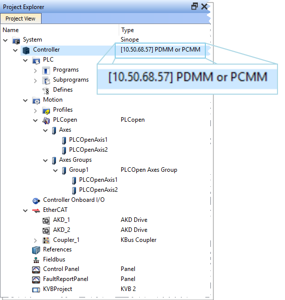
Figure 3-2: Project Explorer with Controller type and IP address.
-
-
You can navigate in the project-tree by entering the item's initial letter, or by means of the arrow keys.
A project is made of several items that are:
System
This item concerns the whole project. A right-click opens its menu that provides the following options:
| Command | Description |
|---|---|
| Add HMI Device | Add a new HMI device with a KVB panel. For mode details see HMI Device below. |
Table 3-1: System Node - Contextual Menu
 [Top]
[Top]Controller
This item displays the controller's IP address and controller hardware type. It is also used to Access the WebServer From the IDE. The webserver functionality may be used directly within the IDE. For more information on the webserver see Using the KAS Web Server.
-
-
Please note that the IP address is shown as
127.0.0.1if the system is in simulation mode.
| Command | Description |
|---|---|
| Add Control Panel | Add a new contol panel to the controller. For more details see Control Panel. |
| Add KVB Project | Add a new KVB panel which is embedded into the contoller. For more details see KVB Project. |
| Import KVB Project |
Import a compressed ("zipped") KVB project, which may be created in KAS or KVB. The system will validate the compressed KVB project and add the panel. |
| Import Control Panel | Import a pre-configured control panel for use in the project. See Import a Control Panel for more information. |
| Add Fieldbus | Add a node to access the Fieldbus Editor. See for more information. |
| Access Web Server | This command opens the web server interface in the GUI |
| Properties |
Open a dialog box to configure the controller. See Configure the Controller for a full description of this dialog box.
Figure 3-3: Configure the Device Parameters Description
|
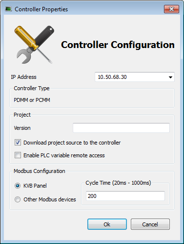

Table 3-2: Controller Node - Contextual Menu
A controller is composed of a PLC item, a Motion item, control panels, an EtherCAT Motion Bus and some References. These items are described in the following sections.
PLC
This item contains all the PLC (Virtual Machine) part of the controller. The following items can be present in this item:
- Program items
- Subprogram items
- Some "Defines"
| Command | Description |
|---|---|
| Libraries | Import new libraries |
Table 3-3: PLC Node - Contextual Menu
Programs
| Command | Description |
|---|---|
| New Program | Add new program items (SFC,ST,FBD, IL or FFLD) |
| Cycle | Configure the cycle of the virtual machine For mode details on Cycle, see "Define the PLC Cycle" |
| Import | Import a saved program |
Table 3-4: Program Node - Contextual Menu
-
-
Programs and Subprograms can be reordered by drag-and-drop. Dragging an item up the list places it above the program you drop it on, while dragging down places it below.
| Command | Description |
|---|---|
| Add Child SFC |
Add a child program to this program. Note that this is reserved for the first SFC program only. |
| Import Child SFC |
Import a saved SFC program to the current program. Note that this is reserved for the first SFC program only.
Please note that only local variables are copied (not the global variables) |
| Export |
Save the selected program to your file server, avoiding spaces in the file name. |
| Rename | Rename the selected program. |
| Delete | Delete the selected program. |
| Print SFC and All Level 2 | Print all PLC programs. See Print for more details. |
Table 3-5: Program Item - Contextual Menu
-
-
You can double-click to open the program in the workspace.
Subprograms
| Command | Description |
|---|---|
| New Function (Subprogram) | Add a new subprogram item (ST,FBD, IL or FFLD) |
| New UDFB |
Add a new UDFB item (ST,FBD, IL or FFLD) |
| Import | Import a saved program |
Table 3-6: Subprogram Node - Contextual Menu
You can create your own functions as well as functional blocks that are called UDFBs (User-Defined Functional Blocks). For each of them, you can use the following commands:
| Command | Description |
|---|---|
| Export | Save the selected subprogram onto your file server |
| Rename | Rename the selected subprogram |
| Create Unlocked Copy | Duplicate the selected, locked subprogram. The duplicate will not be locked. |
| Delete | Delete the selected subprogram |
| In/Out Parameters | Open the Program Properties dialog box to Declare Functions or Function Blocks. This item is disabled for locked UDFBs. |
Table 3-7: Subprogram Item - Contextual Menu
-
-
You can double-click to open the subprogram in the workspace.
Defines
This item contains all the global definitions in the scope of the corresponding device.
-
-
You can double-click a Define item to show these global definitions. A file of internal defines can be found in
[the installation directory of the KAS IDE]\Astrolabe\Bin\HwDef\lib.eqv.
Motion
The motion item contains the motion-specific items (i.e. the Profiles and PipeNetwork items).
| Command | Description |
|---|---|
| Motion Engines | Choose the motion engine for your application between PLCopen and PipeNetwork |
Profiles
This item contains all the cam profiles in the project.
| Command | Description |
|---|---|
| New Profile | Create a new cam profile and add it to this device (*.csv, *.cam) For mode details, see "Adding Cam Profiles" |
| Import | Import already existing cam profiles to your project |
| Show compiled code | Show the code corresponding to the selected cam profile |
Table 3-8: Profiles Node - Contextual Menu
Right-clicking on a cam profile provides additional commands.
| Command | Description |
|---|---|
| Rename | Provide the cam profile a unique name |
| Delete | Remove the cam profile from the list |
| Export | Save the cam profile in CAM (.cam) format |
| Properties | Open a dialog to modify the cam profile's Master/Input Slave/Output Offset and Scale values. |
For more information on cam profiles see Adding Cam Profiles and Cam Profile Editor.
Pipe Network
This menu applies to the Pipe Network in the project.
| Command | Description |
|---|---|
| Import and replace |
This command replaces the existing Pipe Network with a pre-saved Pipe Network. You will be presented with a dialog box to locate the pre-saved file. The Pipe Network Editor will be opened when the file is imported. |
| Export |
Export the Pipe Network to a file for reuse. |
| Show compiled code | Show the code corresponding to the Pipe Network |
-
-
The existing EtherCAT axis mapping is lost when using Import and replace. Additionally, profiles assigned to Cam blocks are cleared at this time.
- Double-click on EtherCAT in the Project View to open the EtherCAT Devices tab tab so you can reassign the axes.
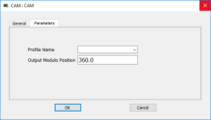
- Double-click on any Cam blocks, and set the Profile_Name parameter.
-
-
You can double-click to open the Pipe Network in the workspace.
PLCopen
| Command | Description |
|---|---|
| New Axis | Add a new axis to your project For mode details, Create PLCopen Axis |
| Show compiled code | Show the code corresponding to the PLCopen |
Table 3-9: PLCopen Node - Contextual Menu
Axes
Each axis is listed here, whether it is found via a scan of the EtherCAT network, or added manually. To add an axis manually, right-click and select New Axis. For each PLCopen axis you can use the following commands:
| Command | Description |
|---|---|
| Properties | Open a dialog box to configure the PLCopen axis data |
| Delete | Delete the selected axis |
Table 3-10: Axis Item - Contextual Menu
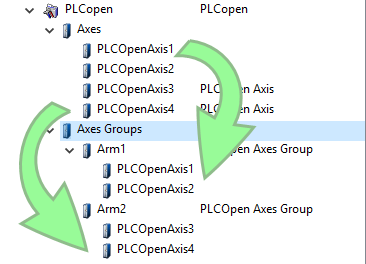
Axes Groups
Axes Groups are collections of related axes defined as the data type AXIS_GROUP_REF, typically used by coordinated motion and function blocks such as MC_SetKinTra. Right-click on this section to create a new Axes Group. Groups are populated by dragging an existing axis from the above section into the group.
The following commands are available by right-clicking on a group.
| Command | Description |
|---|---|
| Delete | Delete the selected Axes Group |
| Rename | Change the name of the Axes Group. |
Control Panel
This item holds the Control Panel item used to provide a basic interface between you and the virtual machine.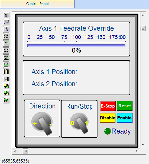
- For more details, Design the Control Panel with the Internal Control Panel Editor
- For a more advanced tool to build HMI, KVB Project
| Command | Description |
|---|---|
| Rename | Rename the selected Control panel |
| Delete | Delete the selected Control panel |
| Export | Export the control panel for use in other projects. See Export a Control Panel. |
Table 3-11: HMI Control Panel Node - Contextual Menu
-
-
You can double-click to open the Control Panel in the workspace.
Controller Onboard I/O
| Command | Description |
|---|---|
| Properties |
Open the Properties dialog box to configure the local I/O for the PDMM or PCMM controller. |
Table 3-12: Controller Onboard I/O Item - Contextual Menu
EtherCAT
This item gives access to all the devices linked to the EtherCAT Motion Bus.
| Command | Description |
|---|---|
| Add Device… | Add a Kollmorgen drive, power supply, or coupler, pr a third-party EtherCAT device to the EtherCAT node in the Project view. |
| Scan Devices | TheKAS Runtime sends EtherCAT messages to discover the devices present in the network EtherCAT Devices tab |
| Enable/Disable Online Configuration Mode | Toggles Online Configuration Mode on and off. See Online Configuration Mode for more information. |
| Properties | Open the Properties dialog box. Configure EtherCAT Motion Bus |
Table 3-13: EtherCAT Node - Contextual Menu
Add & Configure Third Party Devices
AKD Drive
You can double-click an AKD to set its parameters. Configure the AKD Drive
| Command | Description |
|---|---|
| Rename | Rename the selected drive |
| Delete | Delete the selected drive |
| Configuration | Opens the Configuration tab for the AKD GUI. |
| Properties | Select the Properties menu to access the EtherCAT device's configuration views. |
Table 3-14: AKD Drive Item - Contextual Menu
AKD-C Central Power Supply
You can double-click an AKD-C to set its parameters. Configure the AKD Drive
| Command | Description |
|---|---|
| Rename | Rename the selected device |
| Delete | Delete the selected device |
| Properties | Select the Properties menu to access the EtherCAT device's configuration views. |
| Configuration | Opens the Configuration tab for the AKD GUI. |
Table 3-15: AKD-C Drive Item - Contextual Menu
AKD-N Drive
You can double-click an AKD-N to set its parameters. Configure the AKD Drive
| Command | Description |
|---|---|
| Rename | Rename the selected drive |
| Delete | Delete the selected drive |
| Properties | Select the Properties menu to access the EtherCAT device's configuration views. |
| Configuration | Opens the Configuration tab for the AKD GUI. |
Table 3-16: AKD-N Drive Item - Contextual Menu
Standard I/O Coupler
The Standard I/O Coupler node gives access to its I/O slices.
| Command | Description |
|---|---|
| Add I/O Slice | Add a new slice (Digital or Analog Input and Output) to the selected Standard I/O Coupler |
| Rename | Rename the selected coupler |
| Delete | Delete the selected coupler |
| Properties | Select the Properties menu to access the EtherCAT device's configuration views. |
Table 3-17: Standard I/O Coupler Node - Contextual Menu
Note that all those commands are disabled when the controller is running.
See EtherCAT Coupler Error Handling And Diagnosis in the Troubleshooting section for information about diagnosing the coupler LEDs.
I/O Slice
| Command | Description |
|---|---|
| Properties |
Open the Properties dialog box to configure the I/O slice |
| Rename | Rename the selected slice |
| Delete | Delete the selected slice |
Table 3-18: I/O Slice - Contextual Menu
Device
Double-clicking a Device accesses its EtherCAT device configuration views.
| Command | Description |
|---|---|
| Rename | Rename the selected device |
| Delete | Delete the selected device |
| Add Module… | Add a module to an MDP device. Add Modules to Third Party EtherCAT Devices. |
| Properties | Access the EtherCAT device's configuration views |
Table 3-19: Device - Contextual Menu
Module
| Command | Description |
|---|---|
| Rename | Rename the selected module. |
| Delete | Delete the selected module. |
References
This item allows you to insert references into your project. Each reference is a user-defined reference that links any kind of deliverable to your project (for more details, refer to Use the Reference Folder)
| Command | Description |
|---|---|
| Insert Reference | Link any kind of deliverable to your current project |
| Delete | Delete the reference |
| Properties | Open the referenced file in the workspace |
Table 3-20: Reference Node - Contextual Menu
-
-
You can double-click to open the Reference in the workspace.
Fieldbus
This item holds the Fieldbus Editor to configure the Ethernet![]() Ethernet is a large, diverse family of frame-based computer networking technologies that operate at many speeds for local area networks (LANs)/IP or Profinet fieldbuses
Ethernet is a large, diverse family of frame-based computer networking technologies that operate at many speeds for local area networks (LANs)/IP or Profinet fieldbuses![]() A Fieldbus is an industrial network system for real-time distributed control (e.g. CAN or Profibus). It is a way of connecting instruments in a plant design. For mode details,
A Fieldbus is an industrial network system for real-time distributed control (e.g. CAN or Profibus). It is a way of connecting instruments in a plant design. For mode details,
HMI Device
This item holds the HMI (Human Machine Interface) item used to provide an advanced interface between you and the virtual machine.
| Command | Description |
|---|---|
| Add KVB Project | Add a new KVB panel to the controller. For mode details, Add an HMI Device Note that this command is disabled when a KVB panel already exists |
| Import KVB Project |
Import a compressed ("zipped") KVB project, which may be created in KAS or KVB. The system will validate the compressed KVB project and add the panel. |
| Rename | Rename the selected HMI device |
| Delete | Delete the selected HMI device |
Table 3-21: HMI Device Node - Contextual Menu
KVB Project
| Command | Description |
|---|---|
| Rename | Rename the selected KVB panel |
| Delete | Delete the selected KVB panel |
| Export | Save a copy of the panel in a compressed (.zip) file. |
Table 3-22: KVB Panel Node - Contextual Menu
-
-
You can double-click to open the KVB panel in Kollmorgen Visualization Builder


